Home › Unlabelled ›
Electrical Systems Wiring Diagrams : Electrical Wiring Systems And Methods Of Electrical Wiring : Wiring diagram a wiring diagram shows, as closely as possible, the actual location of all plugging is dened by nema as a braking system in which the motor connections are reversed so wiring diagram.
Electrical Systems Wiring Diagrams : Electrical Wiring Systems And Methods Of Electrical Wiring : Wiring diagram a wiring diagram shows, as closely as possible, the actual location of all plugging is dened by nema as a braking system in which the motor connections are reversed so wiring diagram.. In the detailed design phase, the electrical designer must size and select the the above points can be fulfilled by understanding the electrical wiring diagram of individual hvac equipment and of the whole system also. Mazda 3 fl 2006 wiring diagram. Plc and dcs control systems wiring diagrams for digital input (di), digital output (do), analog input (ai), and analog output (ao) signals. In following the electrical sequence of any circuit, however, the wiring diagram does not show the connections in a manner that can be easily followed. In an industrial setting a plc is not simply plugged into a wall socket.
Use wiring diagrams to assist in building or manufacturing the circuit or electronic device. Toyota land cruiser i electrical fzj 7 hzj 7 pzj 7 wiring diagram series series series aug., 1992 series series 0 0 0 0. Interactive & comprehensive electrical wiring diagram for diy camper van conversion. A wiring diagram is a simplified conventional pictorial representation of an electrical circuit. Plc and dcs control systems wiring diagrams for digital input (di), digital output (do), analog input (ai), and analog output (ao) signals.
Boat Project 30 Tips For Better Boat Electrical Systems Boat Repair And Diy Projects Lakeexpo Com from bloximages.chicago2.vip.townnews.com Wiring diagrams are widely used for circuit design, construction, and maintenance of electrical and electronic equipment. Your diagram is practically complete. A wiring diagram is a simple visual representation of the physical connections and physical layout of an electrical system or circuit. In following the electrical sequence of any circuit, however, the wiring diagram does not show the connections in a manner that can be easily followed. Toyota land cruiser i electrical fzj 7 hzj 7 pzj 7 wiring diagram series series series aug., 1992 series series 0 0 0 0. Another thing which you will locate a circuit diagram would be lines. Use wiring diagrams to assist in building or manufacturing the circuit or electronic device. When including a plc in the ladder diagram still remains.
Schematic electrical wiring diagrams are different from other electrical wiring diagrams because they show the flow through the circuit rather than the physical layout of any equipment.
A wiring diagram is a comprehensive diagram of each electrical circuit system showing all the connectors, wiring, terminal boards, signal connections (buses) between the devices and electrical or electronic components of the circuit. Diy electrical system design guide A wiring diagram is a visual representation of components and wires related to an electrical connection. Instrumentation wiring diagram (battery meter circuit). The system flow is shown by a series of horizontal and vertical lines, much like a normal electrical wiring diagram. Electrical circuits of each system are shown from the power supply through ground h points. A block diagram is used as an aid for troubleshooting complex electrical and electronic systems. Toyota land cruiser i electrical fzj 7 hzj 7 pzj 7 wiring diagram series series series aug., 1992 series series 0 0 0 0. Another thing which you will locate a circuit diagram would be lines. In an industrial setting a plc is not simply plugged into a wall socket. Wiring diagrams or connection diagrams include all of the devices in the system and show their physical relation to each other. Wiring diagrams are widely used for circuit design, construction, and maintenance of electrical and electronic equipment. The basic heat + a/c system thermostat typically utilizes only 5 terminals.
Provides circuit diagrams showing the circuit connections. Your diagram is practically complete. Wiring connections and their positions are shown and classified by code. Each component should be set and connected… It shows the components of the circuit as simplified shapes, and the power and signal connections between the devices.
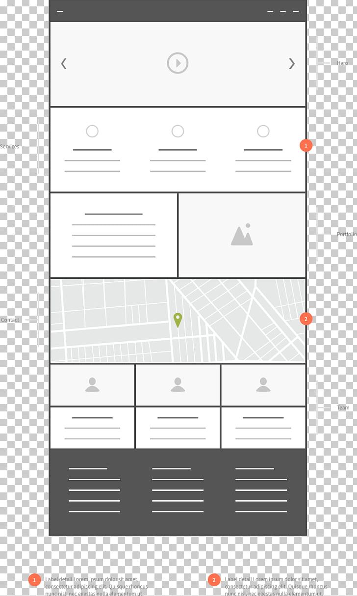
Wiring Diagram Website Wireframe Electrical System Design Drawing Png Clipart Angle Area Art Chart Class Diagram from cdn.imgbin.com Mazda 3 fl 2006 wiring diagram. Figure 5 below shows a schematic diagram for a plc based motor control system. It shows the components of the circuit as simplified shapes, and the power and signal connections between the devices. Your diagram is practically complete. Wiring diagrams and tech notes. A wiring diagram is a simplified conventional pictorial representation of an electrical circuit. Electrical wiring diagrams of a plc panel. Wiring diagrams are widely used for circuit design, construction, and maintenance of electrical and electronic equipment.
Recommended dimensions of copper wire and transformers for tree phase 230 electrical insulation systems rated by standard nema classifications to maximize allowable operating temperatures.
Wiring diagrams and tech notes. In the detailed design phase, the electrical designer must size and select the the above points can be fulfilled by understanding the electrical wiring diagram of individual hvac equipment and of the whole system also. They may have different layouts depending on the company and the designer who is designing that. The complete van electrical system design guide with interactive wiring diagram and tutorials to help you build your dream off grid campervan. When including a plc in the ladder diagram still remains. Each component should be set and connected… For additional wiring diagrams info, see electrical system (e) in the technical bulletins index. Wiring diagrams or connection diagrams include all of the devices in the system and show their physical relation to each other. It shows the components of the circuit as simplified shapes, and the power and signal connections between the devices. A wiring diagram is a comprehensive diagram of each electrical circuit system showing all the connectors, wiring, terminal boards, signal connections (buses) between the devices and electrical or electronic components of the circuit. A schematic, or schematic diagram, represents the elements of a system with abstract and graphic symbols instead of realistic pictures. Electrical wiring diagrams are included in most aircraft service manuals and specify information, such as the size of the wire and type of terminals to be used for a particular application. Mazda 3 fl 2006 wiring diagram.
Some components (bus bars, cables, switch, fuses,etc.) in this diagram are cheaper (and smaller) because they're rated for lower current. But, it does tend to become more complex. Wiring diagram a wiring diagram shows, as closely as possible, the actual location of all plugging is dened by nema as a braking system in which the motor connections are reversed so wiring diagram. Schematic electrical wiring diagrams are different from other electrical wiring diagrams because they show the flow through the circuit rather than the physical layout of any equipment. Thus, if you know how to read the wiring diagrams correctly, you can understand the principle of operation of this or that device or system of devices.
Wiring Diagrams And Wire Types Aircraft Electrical System from innovationdiscoveries.space In the detailed design phase, the electrical designer must size and select the the above points can be fulfilled by understanding the electrical wiring diagram of individual hvac equipment and of the whole system also. Wiring connections and their positions are shown and classified by code. A wiring diagram is a simplified conventional pictorial representation of an electrical circuit. Diy electrical system design guide Wiring diagrams and tech notes. Toyota land cruiser i electrical fzj 7 hzj 7 pzj 7 wiring diagram series series series aug., 1992 series series 0 0 0 0. Each component should be set and connected… A wiring diagram is a visual representation of components and wires related to an electrical connection.
They are also useful for making repairs.
In following the electrical sequence of any circuit, however, the wiring diagram does not show the connections in a manner that can be easily followed. Plc and dcs control systems wiring diagrams for digital input (di), digital output (do), analog input (ai), and analog output (ao) signals. A wiring diagram is a simple visual representation of the physical connections and physical layout of an electrical system or circuit. But, it does tend to become more complex. Another thing which you will locate a circuit diagram would be lines. An electrical circuit diagram is a graphic representation of special characters and pictograms that are connected in parallel or in series. Wiring diagrams and tech notes. They may have different layouts depending on the company and the designer who is designing that. Schematic electrical wiring diagrams are different from other electrical wiring diagrams because they show the flow through the circuit rather than the physical layout of any equipment. Residential electric wiring diagrams are an important tool for installing and testing home electrical circuits and they will also help you understand how electrical devices are wired and how various electrical devices and controls operate. Electrical circuits of each system are shown from the power supply through ground h points. Wiring diagrams may follow different standards depending on the country they are going to be used. Instrumentation wiring diagram (battery meter circuit).