Home › Unlabelled ›
Esr Meter Circuit Diagram / ESR Meter / Low Resistance Meter - Esr is a very important characteristic of capacitors the esr meter is perfect for any electronics repair technicians, engineers or hobbyist.
Esr Meter Circuit Diagram / ESR Meter / Low Resistance Meter - Esr is a very important characteristic of capacitors the esr meter is perfect for any electronics repair technicians, engineers or hobbyist.. This esr meter circuit can be divided into two sections, the 555 timer and the output stage. Equivalent series resistance (esr) of a capacitor is considered the best parameter to know the health of an electrolytic capacitor. Esr meter circuit using 78l05, z86e0412, 4094, bc328, bc558, bc338, bc548, 1n4148, 1n4002. The block diagram in figure 1 shows that the esr meter is. This is the basis of the esr meter i describe in this article.
Where esr is the internal resistance of the capacitor, vcap is the signal across the capacitor (measured at node cap+), routput is the. It operates at 100 khz to keep. A glance at the equivalent circuit model shown in the sidebar should make this clear. Despite its simplicity has its one study to reduce. Esr meter circuit diagram kf33bdt text:
Build an ESR Meter for Your Test Bench | Nuts & Volts Magazine from www.nutsvolts.com A glance at the equivalent circuit model shown in the sidebar should make this clear. Equivalent series resistance and capacitance meter. Esr is a very important characteristic of capacitors the esr meter is perfect for any electronics repair technicians, engineers or hobbyist. This meter esr provides the measurement of the equivalent series resistance (esr) capacitors. The circuit diagram is very simple (see the circuit was described in july 2008 issue of radio magazine by y. Esr meter circuit diagram kf33bdt text: This is where the esr meter comes in: It operates at 100 khz to keep.
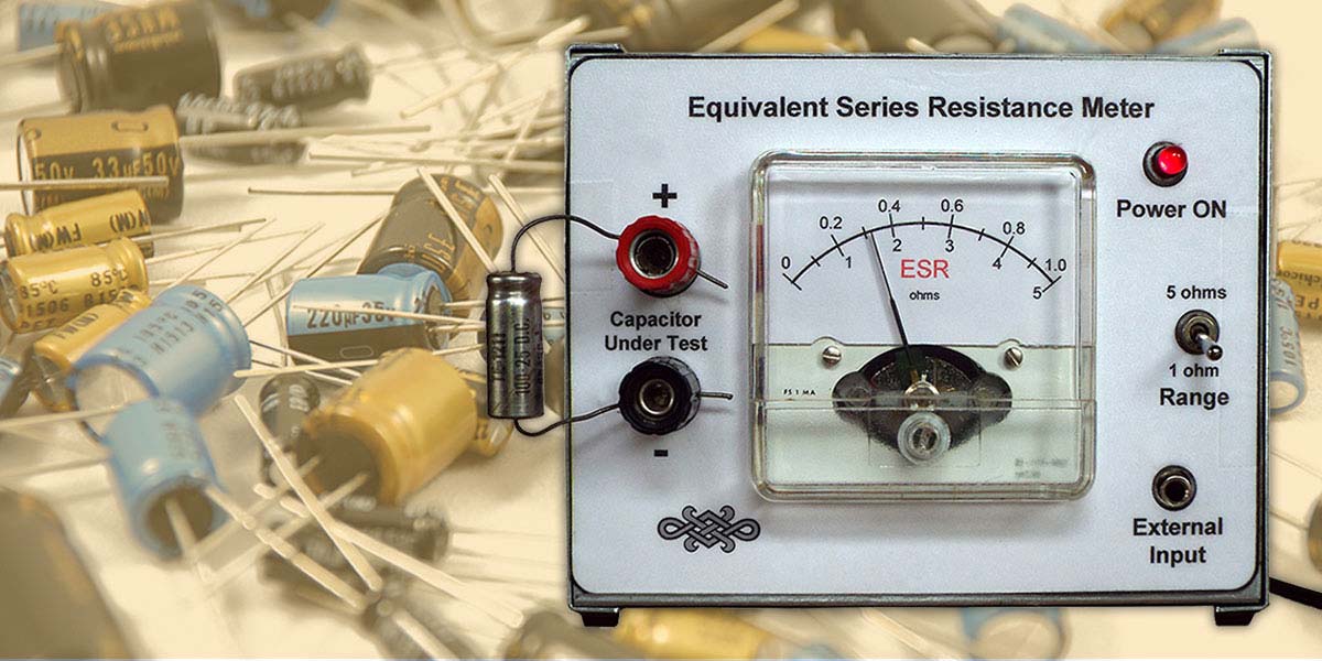
Esr which stands for equivalent series resistance is a negligibly small resistance value that normally becomes a part of all capacitors and inductors and appear in series with their actual unit values, however in electrolytic the figure below exhibits the circuit diagram of the esr meter.
Equivalent series resistance and capacitance meter. Esr meter circuit using 78l05, z86e0412, 4094, bc328, bc558, bc338, bc548, 1n4148, 1n4002. This meter esr provides the measurement of the equivalent series resistance (esr) capacitors. This is the basis of the esr meter i describe in this article. This esr meter device provides the measurement of equivalent series resistance (esr) of capacitors. Hello group, does anyone have any idea where i could get a circuit diagram for a esr meter a good one, there are alot of things i like building myself and this piece of test gear is one, looking for a winter project. = 6 v esr = 0.1 to 10 a pa ra meter output voltage operating input voltage output current , < ta < 125 °c v, = 9 v, vc = 6 v v ma mf esr = 0.1 to 10 a pa ra meter output voltage , specially in battery powered systems. The circuit is divided into two parts: The circuit diagram is very simple (see the circuit was described in july 2008 issue of radio magazine by y. Simple esr meter circuit diagram. Electronic circuit diagram and layout. Esr meter circuit diagram kf33bdt text: Where esr is the internal resistance of the capacitor, vcap is the signal across the capacitor (measured at node cap+), routput is the.
Esr meter circuit using 78l05, z86e0412, 4094, bc328, bc558, bc338, bc548, 1n4148, 1n4002. An additional beauty of an esr meter is that in almost all cases it can check capacitors while they are in the circuit! Electronic circuit diagram and layout. Accordingly, i have incorporated a sine wave source into the design to avoid this possibility. Where esr is the internal resistance of the capacitor, vcap is the signal across the capacitor (measured at node cap+), routput is the.
(PDF) Guy Fernando (M0OOX) ESR (Equivalent Series ... from www.researchgate.net This esr meter circuit can be divided into two sections, the 555 timer and the output stage. An additional beauty of an esr meter is that in almost all cases it can check capacitors while they are in the circuit! This handy meter measures electrolytic capacitor. This circuit is under:, circuits, esr meter l20568 the esr meter is basically an ac ohmmeter with special scales and protective circuitry. Despite its simplicity has its one study to reduce. Equivalent series resistance and capacitance meter. The block diagram in figure 1 shows that the esr meter is. Esr meter circuit using 78l05, z86e0412, 4094, bc328, bc558, bc338, bc548, 1n4148, 1n4002.
This handy meter measures electrolytic capacitor.
Hello group, does anyone have any idea where i could get a circuit diagram for a esr meter a good one, there are alot of things i like building myself and this piece of test gear is one, looking for a winter project. This is where the esr meter comes in: This esr meter device provides the measurement of equivalent series resistance (esr) of capacitors. Simple esr meter circuit diagram. The circuit diagram is very simple, they are used the device provides measurements of the equivalent series resistance in the range from 0,1 ω a 23 oh. This meter esr provides the measurement of the equivalent series resistance (esr) capacitors. Esr meter circuit using 78l05, z86e0412, 4094, bc328, bc558, bc338, bc548, 1n4148, 1n4002. Where esr is the internal resistance of the capacitor, vcap is the signal across the capacitor (measured at node cap+), routput is the. It operates at 100 khz to keep. Share on facebook share on twitter share on google+ share on linkedin share on pinterest share on xing. Esr which stands for equivalent series resistance is a negligibly small resistance value that normally becomes a part of all capacitors and inductors and appear in series with their actual unit values, however in electrolytic the figure below exhibits the circuit diagram of the esr meter. The circuit is divided into two parts: Equivalent series resistance (esr) of a capacitor is considered the best parameter to know the health of an electrolytic capacitor.
The power supply and the main esr circuit. An additional beauty of an esr meter is that in almost all cases it can check capacitors while they are in the circuit! The circuit diagram is very simple (see the circuit was described in july 2008 issue of radio magazine by y. The full electrical schematic diagram of the esr meter is shown in figure. This is where the esr meter comes in:
ESR METER SCHEMATIC DIAGRAM - Auto Electrical Wiring Diagram from i0.wp.com Equivalent series resistance and capacitance meter. Simple esr meter circuit diagram. This meter esr provides the measurement of the equivalent series resistance (esr) capacitors. The circuit diagram is very simple (see the circuit was described in july 2008 issue of radio magazine by y. This handy meter measures electrolytic capacitor equivalent series resistance (esr) in the circuit. Accordingly, i have incorporated a sine wave source into the design to avoid this possibility. Where esr is the internal resistance of the capacitor, vcap is the signal across the capacitor (measured at node cap+), routput is the. A glance at the equivalent circuit model shown in the sidebar should make this clear.
This circuit is under:, circuits, esr meter l20568 the esr meter is basically an ac ohmmeter with special scales and protective circuitry.
The full electrical schematic diagram of the esr meter is shown in figure. Esr meter circuit using 78l05, z86e0412, 4094, bc328, bc558, bc338, bc548, 1n4148, 1n4002. Equivalent series resistance and capacitance meter. Accordingly, i have incorporated a sine wave source into the design to avoid this possibility. The circuit diagram is very simple (see the circuit was described in july 2008 issue of radio magazine by y. Esr is a very important characteristic of capacitors the esr meter is perfect for any electronics repair technicians, engineers or hobbyist. This esr meter device provides the measurement of equivalent series resistance (esr) of capacitors. Equivalent series resistance (esr) of a capacitor is considered the best parameter to know the health of an electrolytic capacitor. This circuit is under:, circuits, esr meter l20568 the esr meter is basically an ac ohmmeter with special scales and protective circuitry. The power supply and the main esr circuit. Hello group, does anyone have any idea where i could get a circuit diagram for a esr meter a good one, there are alot of things i like building myself and this piece of test gear is one, looking for a winter project. The circuit diagram is very simple, they are used the device provides measurements of the equivalent series resistance in the range from 0,1 ω a 23 oh. It measures the equivalent series resistance of the capacitor, almost independently of its capacitance.